Frame Relay
Frame Relay is layer 2 packet-switched network protocol, it creates circuits between end-point devices:
- Switched Virtual Circuits (SVC) - Established dynamically by sending signaling messages to the network (CALL SETUP, DATA TRANSFER, IDLE, CALL TERMINATION).
- Permanent Virtual Circuits (PVCs) - preconfigured by the carrier, and after they are set up, only operate in DATA TRANSFER and IDLE modes. Note that some publications refer to PVCs as private VCs.
- DLCI (data link connection identifier)
- DLCI has no significance beyond the single link
- 0 to 15 and 1,008 to 1,023 are reserved, typically the range of 16 to 1,007 is used by customers
Inverse Address Resolution Protocol (Inverse ARP) - resolves IPv4 to DLCI therefore IPv4 addresses must be available before VCs can be used. Frame Relay for IPv6 uses Inverse Neighbor Discovery (IND) to obtain a Layer 3 IPv6 address from a Layer 2 DLCI
Local Management Interface (LMI) - a definition of the messages used between the DTE (R1) and the DCE (the Frame Relay switch owned by the service provider). It is a keepalive mechanism that provides status information, every 10s pulls info from the network. LMI types are: CISCO, ANSI, Q933A
Configuration
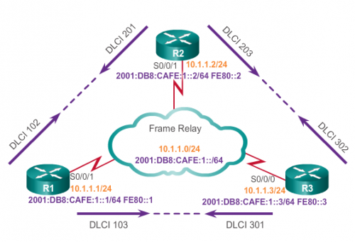
R1(config)# interface S0/0/1
R1(config-if)# bandwidth 64                                !for OSPF, EIGRP and others routing protocols
R1(config-if)# ip address 10.1.1.1 255.255.255.0
R1(config-if)# ipv6 address 2001:db8:cafe:1::1/64
R1(config-if)# ipv6 address fe80::1 link-local
R1(config-if)# encapsulation frame-relay
R1(config-if)# no frame-relay inverse-arp                  !disables iarp
R1(config-if)# frame-relay map ip 10.1.1.2 102 broadcast   !broadcast is to help routing protocols to broadcast its updates on NBMA networks
R1(config-if)# frame-relay map ipv6 2001:DB8:CAFE:1::2 102
R1(config-if)# frame-relay map ipv6 FE80::2 102 broadcast
R2(config) interface S0/0/1
R2(config-if)# bandwidth 64
R2(config-if)# ip address 10.1.1.2 255.255.255.0
R2(config-if)# ipv6 address 2001:db8:cafe:1::2/64
R2(config-if)# ipv6 address fe80::2 link-local
R2(config-if)# encapsulation frame-relay
R2(config-if)# no frame-relay inverse-arp
R2(config-if)# frame-relay map ip 10.1.1.1 201 broadcast
R2(config-if)# frame-relay map ipv6 2001:DB8:CAFE:1::1 201
R2(config-if)# frame-relay map ipv6 FE80::1 201 broadcast
Configuration with sub-interfaces
Frame Relay cloud in fact is a FR switch holding PVC to a port maps. Its configuration is shown below.
R1(config)# interface S0/0/1
R1(config-if)# encapsulation frame-relay
R1(config-if)# no shutdown
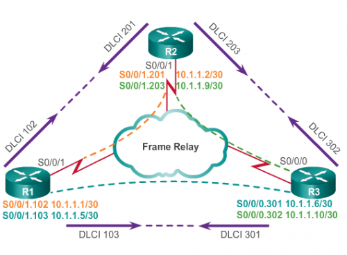
R1(config-if)# interface s 0/0/1.102 point-to-point    !ptp is to help resolve split horizon and other issues with NBMA networks
R1(config-subif)# ip address 10.1.1.1 255.255.255.252
R1(config-subif)# bandwidth 64
R1(config-subif)# frame-relay interface-dlci 102
R1(config-fr-dlci)# exit
R1(config-subif)# R1(config-if)# interface s 0/0/1.103 point-to-point
R1(config-subif)# ip address 10.1.1.5 255.255.255.252
R1(config-subif)# bandwidth 64
R1(config-subif)# frame-relay interface-dlci 103
Routing considerations
Point-to-Point Subinterfaces - In hub and spoke topologies:
- Subinterfaces act as leased lines
- Each point-to-point subinterface requires its own subnet
Multipoint Subinterfaces – In partial-mesh and full-mesh topologies:
- Subinterfaces act as NBMA so they do not resolve the split horizon issue
- routers exist in the same subnet
Troubleshooting
Changing configuration requires power cycling an interface
show frame-relay map
show frame-relay lmi
show interfaces serial
show frame-relay pvc
clear counters
clear frame-relay inarp
! ACTIVE - DTE to DCE (router to a Frame Relay switch) circuit
! INACTIVE - connected to DCE (switch) but without DTE detected at the other end
! DELETED - switch doesn't recognize DLCI configured on a router as a valid for its interface
debug frame-relay lmi

